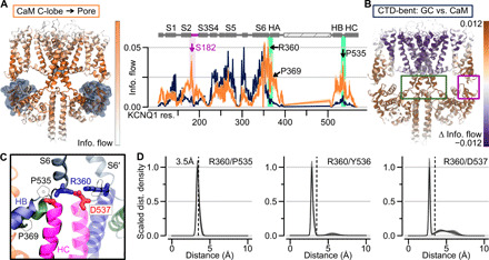
Fig. 5. A hub in the KCNQ1 CTD cooperates with the CaM-VSD interactions to control AO state occupancy.

(A) Left: Information flow projection onto the CTD-bent structure, capped at 0.02. For clarity, VSDs, HA/HB, and CaMs in the front and back subunits are omitted. Right: Orange, information flow profile along KCNQ1 sequence (CaM C-lobe used as the source) in the CTD-bent structure; dark blue, information flow profile with gating charges as source. Purple shading, information flow peak in the S2-S3 linker/CaM interface. Green shading, peak between the HB/HC and HA/S6 loops. (B) Δinformation flow projected on the CTD-bent structure (CaM C-lobe versus the gating charges as the source). Dark violet residues, decreased information flow as a result of using CaM C-lobe as source; brown, increased information flow. (C) Structural depiction of residues in the CTD hub. Green ribbons, HA; blue ribbons, HB; pink ribbons, HC; gray ribbons, S6. S6′ is from a neighboring subunit. Residues depicted with sticks are colored according to residue type: positively (negatively) charged, blue (red); hydrophobic, white. (D) Scaled distance density of interacting residues in the CTD hub.
