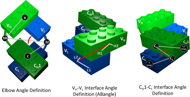
FIGURE 1.
Elbow angle, ABangle (HL angle), and CH1–CL interface angle definitions depicted as Lego models. The constant domains are illustrated in dark green (CH1) and dark blue (CL), while the variable domains are shown in light green (VH) and light blue (VL). To calculate the CH1–CL interface angle, we defined a torsion angle between the center of mass of the C-terminal loops of the CH1 domain, the center of mass of CH1, the center of mass of the CL domain, and the center of mass of the C-terminal loops of the CL domains. The center of masses of the CH1 and CL C-terminal loops are depicted in this figure, as CL and CH1 loops. For the elbow angle definition, all used centers of mass to define the torsion angle are illustrated. The centers of mass of the switch or hinge regions are abbreviated with hh (hinge heavy) and hl (hinge light).

