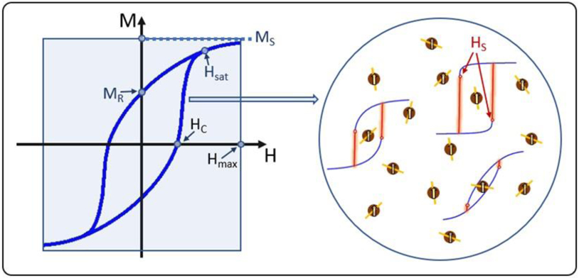
Figure 2: Schematic ol magnetic Hysteresis ana heating by torced hysteisis in an alternating magnetic field.

(Left) A diagram of an idealized hysteresis loop showing the characteristic parameters (MS, MR, HC, and Hsat) relevant for heat generation for magnetic hyperthermia. (Right) Illustration of the microscopic origin of the global field-dependent magnetization. M(H), of an idealized ensemble of non-interacting (single-domain) magnets (nanoparticle), some of which contain a representative cartoon of M(H) highlighting that the hysteresis loop of each panicle may significantly differ from that of other magnets. Differences depicted here arise from the relative orientations of each magnet’s moment (M) about its easy-axis orientation (represented by the yellow lines within each particle). Also depicted are the single-particle characteristic switching field (HS). which does not apply to the left average loop. The red vertical branches illustrate that heat is only dissipated on those irreversible portions.
