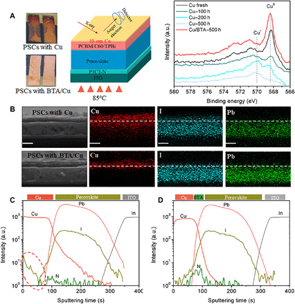
Fig. 4. Cu electrode corrosion in PSCs under device aging.

(A) Photographs of aged PSCs and AES variation of Cu LLM in PSCs. Note that in AES characterization, only a 10-nm Cu electrode was used to simulate the situation around the C60(TPBi)/Cu interface in real PSCs during 85°C aging in glove box. (B) Cross-sectional EDX mapping of Cu, I, and Pb elements in aged PSCs. Scale bars, 500 nm. (C and D) ToF-SIMS for depth profiling in aged PSCs with (C) Cu and (D) BTA/Cu after aging at 85°C for 500 hours in a glove box. Marked region indicates the I aggregation. Photo credit: Xiaodong Li, East China Normal University.
