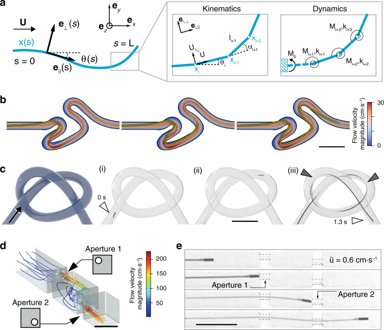
Fig. 3. Simulation of the µ-probe dynamics and adaptive navigation.
a The µ-probe deforming in two-dimensional space is described by the centreline coordinate s and a material reference frame characterized by {e⊥, e||}. The fluid velocity is denoted by U. Discretized model of the µ-probe is shown on the right. This model is used to calculate the velocities and forces. Deformation is calculated iteratively at each node from the resultant torque, M and spring coefficient, k. b Simulations showing the advancement of the μ-probe in the same tortuous channel shown in Fig. 2a and Supplementary Movie 1. c Schematic illustration of a 3D channel with the knot shape and time-lapse images of the µ-probe (i–iii) advancing through a channel with the same geometry. The μ-probe successfully reached the target location in 1.3 s with a forward velocity of 4 cm⋅s−1. Grey arrows indicate points of contact with the wall. d CFD simulation of the flow in a channel with extreme occlusions. The main channel has 2 mm × 2 mm cross-sectional area and 750-μm-diameter holes were placed on two walls in the top-left and bottom-right corner, respectively. Scale bar, 2 mm e Snapshots from the advancement of the μ-probe inside the structured channel simulated in (d), finding its way through the holes even at very low flow velocity . Scale bars in (b, c and e), 5 mm.

