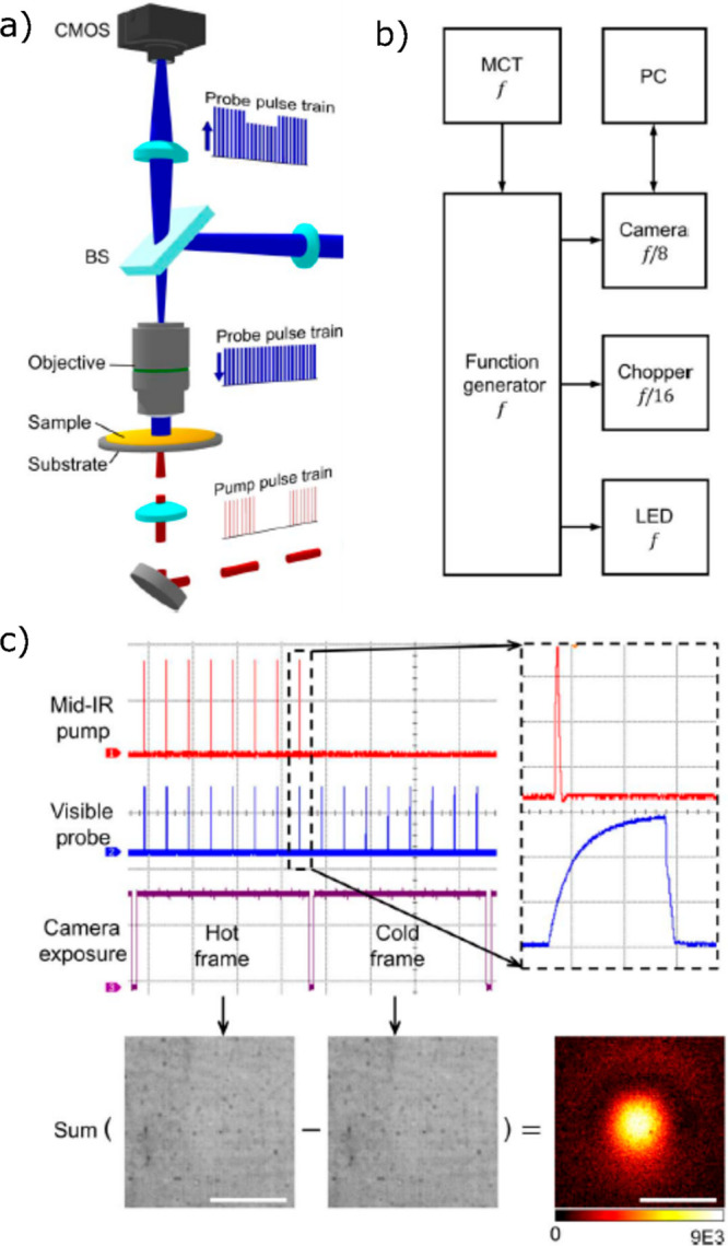
Figure 14.

(a) Schematic representation of the wide-field photothermal setup using the virtual lock-in camera. Pump (red) and probe (blue) pulses propagate in a counter-propagating way. (b) Block diagram showing triggering controls in the virtual lock-in detection. (c) Pump (red) and probe (blue) pulses and camera exposure (purple) with zoomed-in part of the pump and probe pulses (each division of the grid is 100 μs in left non-zoomed-in part and 500 ns in the right-zoomed-in part). Bottom: Image subtraction of the cold frame from the hot frame to obtain a photothermal image. Scale bars: 40 μm. Adapted with permission from ref (61). Copyright 2019 American Association for the Advancement of Science.
