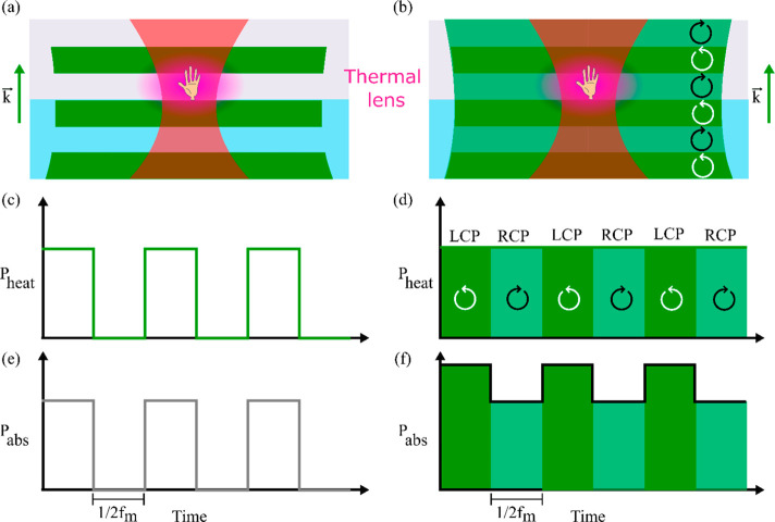
Figure 20.
Schematic of “normal” photothermal (left) and photothermal circular dichroism (right) concept. (a) Scheme of the photothermal detection of a chiral structure (illustrated as a hand) with the wide-field heating. The heating beam (green) is Koehler illuminated, and the probe beam (red) is focused to the diffraction limit. The intensity of the heating beam is modulated between on- and off-states at a frequency fm. The heat released by the heated nanostructure to the environment creates a thermal lens (in purple) around the nanostructure. The wavevector direction (k) for both beams is shown. (b) Scheme for photothermal circular dichroism with modulation of the polarization state of the heating beam between left and right circularly polarized light (dark and light green, respectively). (c) Time evolution of the modulation of the heating power for the “normal” photothermal microscopy, following the intensity modulation pattern at fm. (d) Time evolution of the heating power of the modulated polarized beams for the photothermal circular dichroism microscopy. In this case, the heating power remains constant and only the polarization state changes. (e) Time evolution of the absorbed power by the nanostructure for the “normal” photothermal case. (f) Time evolution of the absorbed power by the nanostructure for the photothermal circular dichroism case. As the nanostructure is chiral, the absorbed powers for LCP and RCP are different. Reprinted from ref (101). Copyright 2019 American Chemical Society.

