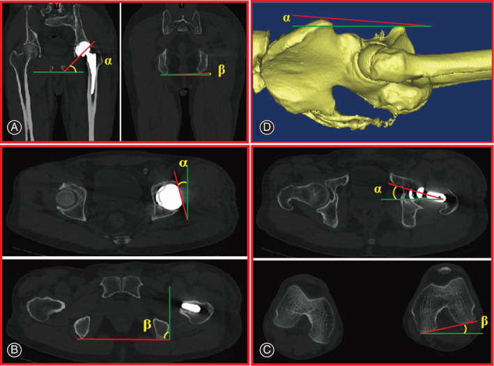
Fig. 2.

Methods used to measure implant orientation and pelvic tilt using CT. The red line is the measured line, while the green line is the reference line. The green lines refer to the horizontal plane in (A), sagittal plane in (B) and (D), and coronal plane in (C) and (D). To minimize the effect of rotation of the pelvis, the angle “β” is used as a reference angle. (A) The inclination of the cup is calculated as (α‐β). (B) The anteversion of the acetabular component is calculated as (α + 90‐β). (C) The anteversion of the stem is calculated as (α + β). (D) Pelvic tilt is calculated as the angle (α) between the line at “the top of the symphysis pubis in the same vertical plane as the anterior superior spine” and the sagittal plane in a 3‐D model.
