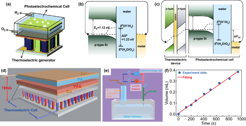
Fig. 12.
a Schematic diagram of a PEC-TE hybrid device. Energy band diagrams of b sole PEC and c a PEC-TE hybrid circuit under illumination depicting the influence of qVTE. Reproduced with permission from Ref. [162]. Copyright 2015 Elsevier Inc., d schematic diagram of the fabricated TENG-TE hybrid energy cell, e schematic diagram of the self-powered system for water splitting to produce H2, f produced volume of H2 at different working times. Reproduced with permission from Ref. [164]. Copyright 2013 Royal Society of Chemistry

