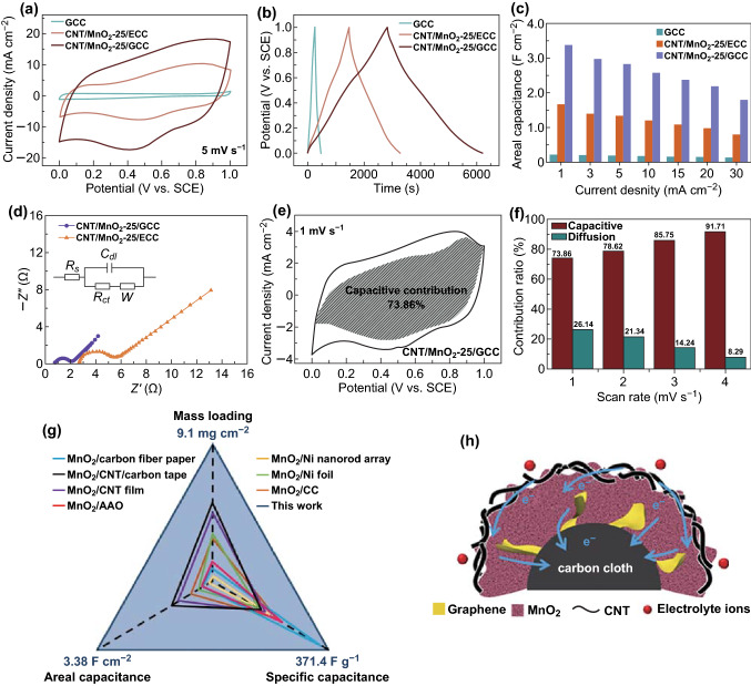
Fig. 3.
a CV curves at a scan rate of 5 mV s−1 within a potential window from 0 to 1 V, b GCD curves at a current density of 1 mA cm−2, and c areal capacitances at different current densities from 1 to 30 mA cm−2 of GCC, CNT/MnO2-25/ECC, and CNT/MnO2-25/GCC electrodes. d Nyquist plots of CNT/MnO2-25/ECC and CNT/MnO2-25/GCC electrodes. Inset: the fitted equivalent circuit. Rs, Rct, W, and Cdl denote equivalent series resistance, charge transfer resistance, Warburg diffusion impedance, and electrochemical double-layer capacitance, respectively. e Capacitive contribution (gray region) to the total charge storage at 1 mV s−1, and f capacitive (red) and diffusion-controlled (green) contribution versus scan rates of the CNT/MnO2-25/GCC electrode. g Capacitance comparison of the CNT/MnO2-25/GCC electrode with previous reports. MnO2/carbon fiber paper [22], MnO2/CNT/carbon tape [23], MnO2/CNT film [24], MnO2/anodic aluminum oxide (AAO) [25], MnO2/Ni nanorod array [26], MnO2/Ni foil [27], MnO2/CC [15]. h The schematic illustration of the CNT/MnO2-25/GCC structure. (Color figure online)

