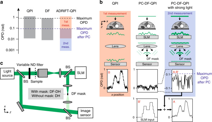
Fig. 1. Principle of ADRIFT-QPI.
a Dynamic range of phase imaging: (left) conventional QPI, (centre) dark-field imaging, (right) ADRIFT-QPI. We assume a standard CMOS image sensor where a full well capacity of ~10,000 e−/pixel is used. b Principle of dynamic range expansion in ADRIFT-QPI. The left column shows the first measurement, where the large-OPD distribution of the sample (B) is measured by QPI with plane wave illumination. The centre column shows the situation of PC-DF-QPI where the DF mask blocks the unscattered light by phase cancellation with the SLM. The right column shows the second measurement, which is PC-DF-QPI with strong light illumination, allowing for dynamic-range-shifted highly sensitive measurement. The dynamic-range-expanded OPD distribution of the sample (A) can be computationally reconstructed by adding the PC-DF-QPI measurement result (A–B′) to the SLM input OPD map (B′). c Optical implementation of ADRIFT-QPI. In this work, off-axis DH is used as a QPI technique. DH and DF-DH are switchable in a single setup by insertion/removal of the DF mask. The phase-only SLM is placed in the sample conjugate plane for wavefront shaping, while the DF mask is placed in the Fourier plane for spatially filtering the unscattered light. The illumination light intensity on the sample can be changed with a neutral density (ND) filter placed in front of the sample. BS: beamsplitter

