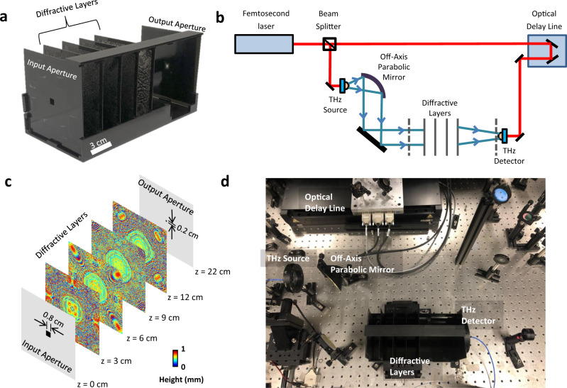
Fig. 1. Schematic of the pulse shaping diffractive network and a photo of the experimental setup.
a 3D printed pulse shaping diffractive network that generates a square pulse with a width of 15.57 ps. b The schematic of the THz-TDS setup used in our experiments. The red line represents the optical path of a 780 nm femtosecond laser, and the blue line represents the terahertz beam. Dashed lines show the input and output apertures of the diffractive network. c The physical system layout of the pulse shaping diffractive network design. The input and output apertures are squares, with edge lengths of 0.8 cm and 0.2 cm, respectively. Gray regions on the aperture planes represent aluminum coating to block light transmission. d The photo of the experimental setup.

