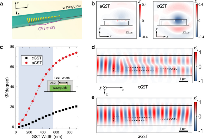
Fig. 1. Design of the phase-gradient metasurface mode converter.
a 3D illustration of the devices. b FDTD simulation of the scattered electric field by one nano-antenna when the GST is in aGST (left panel) and cGST (right panel) phases, respectively, showing the distinctive difference. c. The phase of the scattered mode as a function of the GST nano-antenna width for cGST and aGST phases. The shaded region indicates the range of antenna widths that are used in the phase gradient metasurface. Inset: cross-sectional view of the structure. d, e FDTD simulation results showing effective mode conversion from the TE0 mode to the TE1 mode when the GST is in crystalline phase (d), but only a small perturbation when the GST is in amorphous phase (e).

