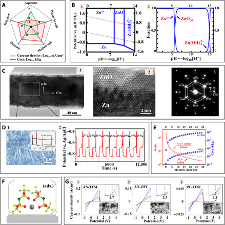
Fig. 4. Designing electrolytes for highly reversible Zn metal plating/stripping.

(A) Spider chart comparing electrolytes for Zn batteries. (B) Distribution of chemical species in aqueous Zn2+ electrolytes. (B-1) Pourbaix diagram. The top and bottom dashed lines represent oxygen evolution and hydrogen evolution reactions (HERs), respectively. (B-2) Fractions of different Zn2+-based species. (C) Transmission electron microscopy (TEM) characterization of Zn electrodeposits. Adapted with permission from (199). (C-1 and C-2) TEM images and (C-3) selected area electron diffraction pattern. (D) Water-in-salt electrolyte for Zn metal deposition. Adapted with permission from (107). (D-1) SEM image of Zn after cycling in water-in-salt electrolyte. (D-2) The plating/stripping voltage profile of Zn in water-in-salt electrolyte. (E) The molality-dependent parameters of high-concentration electrolytes. (F) Schematic diagram showing reaction kinetics of adsorbed (ads.) solvated Zn2+ in acetonitrile (AN) on electrode surface. Adapted with permission from (114). (G) Cyclic voltammetry of organic Zn battery electrolytes: (G-1) AN-Zn(TFSI)2, (G-2) AN-Zn triflate (OTf), and (G-3) propylene carbonate (PC)–Zn(TFSI)2. Adapted with permission from (115).
