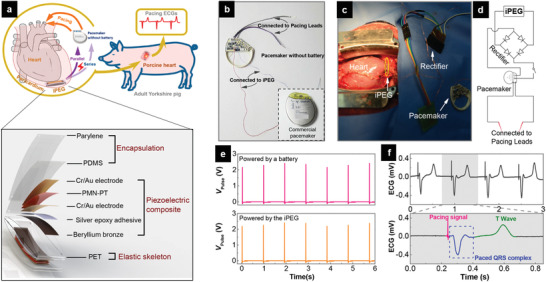
Figure 9.

FEM‐powered cardiac pacemaker. a) The schematic illustration for direct powering a real cardiac pacemaker by utilizing energy from a pig's heartbeat (upper) and the symmetry structure of the implantable iPEG (lower). b) Photograph of a commercial cardiac pacemaker with the onboard lithium battery removed. The inset shows the intact pacemaker. c) Photograph of the implanted iPEG in parallel mode, which is connected to the pacemaker through a rectifier. d) Circuit diagram of the in vivo experiment for powering the pacemaker. e) Comparable pulses released by the pacemaker powered by an external battery (upper) or the implanted iPEG (lower). f) Representative pacing electrocardiograms (ECGs) paced by the iPEG‐powered pacemaker. Upper: The uninterrupted pacing ECGs demonstrating the heart are continuously paced. Lower: An enlarged ECG waveform in one intact cardiac cycle demonstrates that the heart is successfully paced by the iPEG‐powered modern full‐function pacemaker. Reproduced with permission.[ 90b ] Copyright 2019, American Chemical Society.
