
Figure 14.
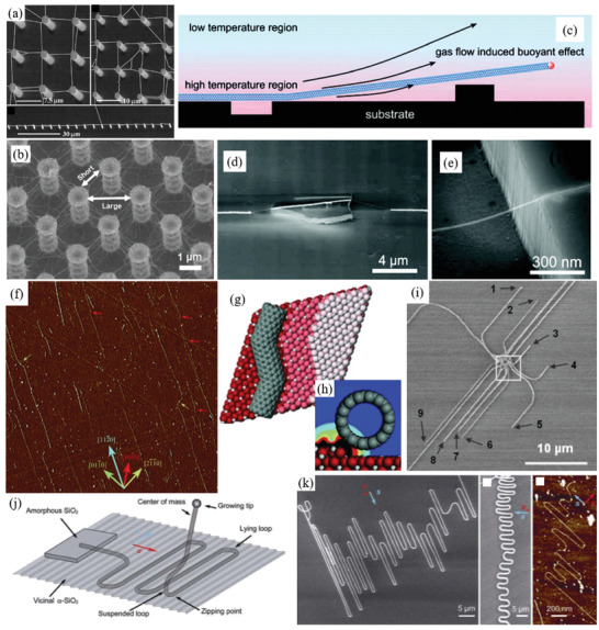
a) SEM images of suspended SWCNTs grown from silicon pillars bridging to other pillars. Reproduced with permission.[ 274 ] Copyright 2000, Wiley‐VCH. b) SEM image of 3D network of SWCNTs suspended between silicon pillars before casting of PDMS. Reproduced with permission.[ 281 ] Copyright 2015, Wiley‐VCH. c) Schematic of the buoyant effect on the growing CNT induced by gas density/temperature gradients in low rate gas flow. Note the growing head of the CNT is raised so it can go over obstacles as it grows. SEM images of d) an SWCNT grown over a raised obstacle and e) an SWCNT grown suspended over a trench. Reproduced with permission.[ 286 ] Copyright 2007, American Chemical Society. f) AFM image and g) model of SWCNTs grown along atomic steps of miscut crystalline sapphire substrates, even growing with kinks to match the atomic steps. The colored arrows on the AFM image indicate the direction of the atomic step edges on the substrate which dictate the growth direction. h) Model of an SWCNT along an atomic step with color gradient representing the interaction energy, demonstrating the increased interaction near the atomic step edge. Reproduced with permission.[ 274 , 288 ] Copyright 2004, Wiley‐VCH. i) SEM image of “sickle” SWCNTs grown from DPN‐patterned Co catalyst island on quartz. “Sickle” SWCNTs grow in random direction initially and then align to crystallographic direction after a certain length. Reproduced with permission.[ 267 , 274 ] Copyright 2008, Wiley‐VCH. j) Proposed growth mechanism of “serpentine” CNT patterns by directing gas flow (red arrow) perpendicular to the crystallographic step edges (“falling spaghetti” mechanism). k) SEM and AFM images of “serpentine” CNT patterns grown on crystallographic substrates. Red and blue arrows indicate gas flow direction and step edge, respectively. Reproduced with permission from open access.[ 288d ] Copyright 2009, Tsinghua University Press and Springer Nature.