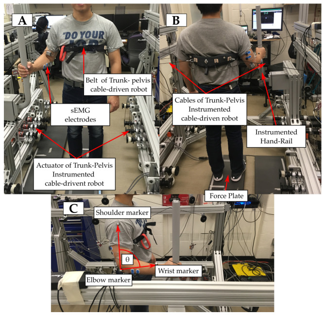
Figure 1.
Overview of the experimental setup. (A) Frontal view of the setup with a subject in the HR condition, showing the grasping pose. Blue frame shows a detail of the same part in HR + E condition. (B) Rear view of the setup shows the placement of the markers that track the position of the end effector of the cable driven robot (belt). (C) Lateral view shows the position of the different markers to estimate the angle of the elbow. Indicators of the position of the different sEMG electrodes are distributed across the three pictures.

