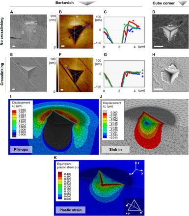
Fig. 2. Nanoindentation of supercrystalline nanocomposites.

(A to D) Indents in the non–cross-linked supercrystalline nanocomposites. (A) SEM micrograph of a 500-nm-deep Berkovich indent. (B and C) AFM topography map and profiles of the indent shown in (A). (D) SEM micrograph of a 300-nm-deep cube-corner indent [reproduced with permission from (7)]. (E to H) Indents in the cross-linked supercrystalline nanocomposites. (E) SEM micrograph of a 500-nm-deep Berkovich indent. (F and G) AFM topography map and profiles of the indent shown in (E). (H) SEM micrograph of a 300-nm-deep cube-corner indent. Scale bars, 500 nm. (I to K) Pile-ups (I), sink-in (J), and equivalent plastic strain (K) resulting from FE simulations of a Berkovich indentation, 500 nm in depth, in the cross-linked material. The visualized subindent cross section is marked in the inset of (K). In (I), the pile-ups are highlighted by only plotting material displacements above the surface, in direction perpendicular to it (z); in (J), the complementary plot is shown.
