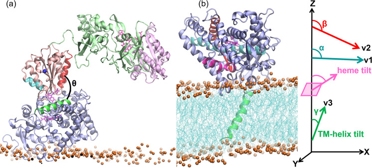
Fig. 2. A CYP 1A1–CPR encounter complex obtained from the rigid-body BD docking simulations is shown superimposed on the structure of CYP 1A1 in a membrane bilayer obtained from MD simulations, which is shown together with the definitions of the angles defining the arrangement of the proteins.
A CYP 1A1–CPR encounter complex (D2) obtained from the rigid-body BD docking simulations is shown in a superimposed on the structure of CYP 1A1 in a membrane bilayer obtained from MD simulations shown in b. The proteins are shown in cartoon representation (CYP globular domain: lilac, TM-helix: green; CPR FMN domain: salmon, FAD domain: pale green, NADP domain: pale pink), cofactors are shown in pink stick representation, and the bilayer is shown in cyan lines with orange spheres representing the phosphorous atoms. The angles defining the arrangement of the proteins are shown: θ is the angle between the CYP C-helix (green) and the FMN domain α1-helix (residues 91–105; red); the FMN domain α3-helix (150–158; cyan) and N-terminal residue of FMN domain (blue sphere) are indicated; the heme-tilt angle is the angle between the heme plane and the z axis perpendicular to the membrane plane; α, β, and γ are the angles between the z axis and the vectors v1, along the I-helix (cyan), v2, orthogonal to v1 and connecting the C-helix (red) and the F-helix (magenta); and v3 along the TM-helix (residues 7–26; green).

