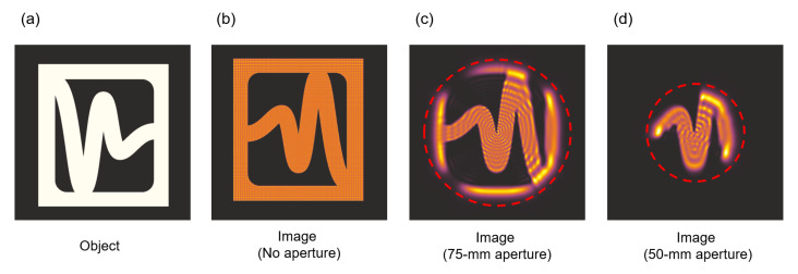
Figure 5.
(a) The exemplary object used in simulations for 0.3 THz. (b) The image obtained in imaging setup assuming no aperture, only calculation matrix size. (c) The image obtained in imaging setup assuming lens apertures limited to 75 mm (marked with red dashed line) (d) The image obtained in imaging setup assuming lens apertures limited to 50 mm (marked with red dashed line). Formed images are inverted as in setups. The presented area corresponds to 90-mm-square area cut from 204.8-mm calculation matrix.

