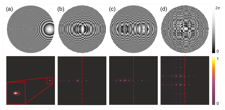
Figure 8.
Different diffractive structures redirecting and splitting the incident radiation. The upper panel illustrates the phase delay maps introduced by each structure. The lower panel illustrates the intensity distribution in the focal plane in (a). Additionally, due to the fact the distributions are symmetrical in (b–d) the focal plane is illustrated as two halves—left corresponding to amplitude distribution and right the intensity distribution. The structure in (a) is a shifted lens to redirect and focus the radiation out of the optical axis. The inset shows the magnification of focal spot which will have more aberrations when shifted further from the optical axis. The structure in (b) is the binary phase grating joined with the converging lens. It forms two strong spots aside optical axis. The structure in (c) is the sinusoidal phase grating joined with the converging lens. Due to the modified changes of the phase the spots corresponding to other order of diffraction than ±1st are also visible. The structure in (d) is the Dammann grating forming the matrix of 3 × 2 points joined with the converging lens. In this case additional orders are very noticeable. Thus, in case of redirecting the beam there in a need to optimized the phase delay map to suppress the influence of undesired spurious focal spots.

