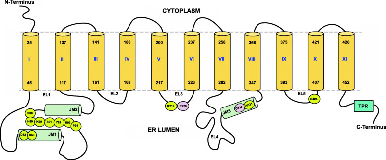
Fig. 2.
Cartoon of the membrane topology of the N-terminal domain of TMTCs and localization of important substructures and residues. The figure shows schematic representation of the overall structural elements and the connectivity of TMTCs. The TM helices are shown in yellow cylinders and marked as I to XI while the helical regions in the lumen are shown in green cylinders and are marked as JM1, JM2 and JM3. The lumenal loops are numbered from EL1 to EL5. The whole TPR region is shown as a single block colored in cyan. The figure also highlights important residues which are (i) the strictly conserved DD motif (M1, Table 4) in EL1 (loop between TM1 and TM2), (ii) conserved SHKSYRP motif (M2, Table 4) also present in EL1, (iii) conserved lysine residue of KET(Q) xxT motif (M4, Table 4) that forms a salt bridge with the phosphate group of DPM, (iv) glutamate residue from conserved KET(Q) xxT motif (M4, Table 4) in EL3 and aspartate residue of the conserved DW motif (M4, Table 4) in EL4, (v) strictly conserved arginine residue from conserved ERxxY motif (M7, Table 4) in loop EL5 between TM9 and T10. All the important residues are colored in yellow except the metal binding residues which are highlighted in pink. The sequence position numbering corresponds to TMTC1. The location of TMs in TMTC1 follows the observations from the 3D structural model created in the course of this work and, at some places, does differ slightly from the sequence-analytic predictions provided in Additional File 2

