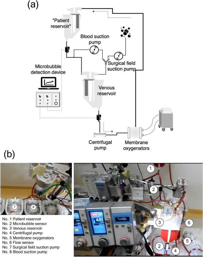
Figure 8.
Experimental setup. (a) A schematic view, and (b) a photo. Given that the blood suction pump draws air, the pump adjusts the blood loss in the surgical field. In actual clinical practice, the surgical field (No. 7) and the blood suction pumps (No. 8) allow the estimation of the total aspirated flow rate in the operative field. Additionally, the microbubble sensor (No. 2) was installed to confirm that no air was mixed in the venous circuit from the patient reservoir, and the other microbubble sensor (No. 2) was attached to the bottom of the reservoir to measure the number of microbubbles. The blood was pumped by the centrifugal pump (No. 4), the flow rate was measured by the corresponding sensor (No. 6), and the blood was returned to the patient reservoir through the membrane oxygenators (No. 5). The patient reservoir was set up to regulate the circulating blood volume. It also contributed to the removal of microbubbles.

