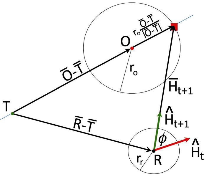
Figure 2.
Geometry of the collection algorithm. The green dot represents the center of the collection zone and is denoted by T. The red dot represents the centroid of the object to be collected, and we denote it by O, and the circle surrounding it at a distance of represents the object boundary. The black dot represents the centroid of the robot, denoted by R, and the circle at a distance of from it represents the robot magnet boundary. The red vector is the current heading of the robot, the green vector is the new heading the robot should move in to approach the collection point (red square) on the far side of the object relative to the target, and is the angle between the current and new heading.

