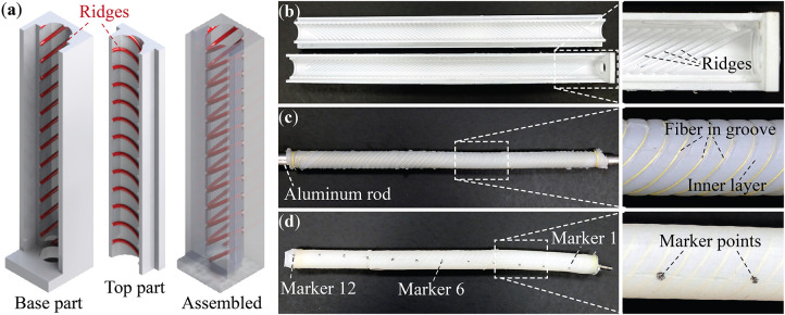
Figure 3.
Fabrication of the plant-inspired coiling actuator. (a) CAD models of a section of the primary molds. The ridges for fiber placement are highlighted. (b) The finished primary molds from 3D printer. (c) The assembly consists of an aluminum rod, cured inner layer, and wrapped Kevlar fiber. (d) A finished coiling actuator. The end adaptor for pressurized air supply and the markers for displacement measurement are highlighted. Note that for every marker shown in this picture, there is another one on the opposite side behind the actuator body.

