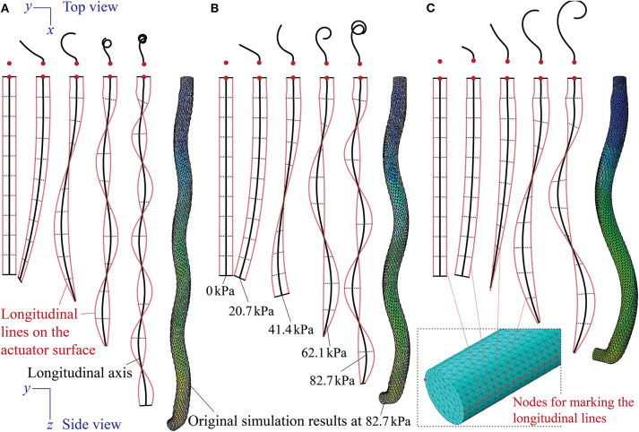
Figure 6.
Finite element simulation of the coiling motions at different pressures from actuators with (A) α = 41°, (B) α = 51°, and (C) α = 61°. Designs of these actuators are the same as the physical prototypes described in Table 1. To trace the deformation of longitudinal lines on the surface, we selected two lines of surface nodes on the opposite sides of the actuator (one of them highlighted in the insert figure) and only showed their displacements at different pressures. The longitudinal axis thus is the averaged displacements of these surface nodes.

