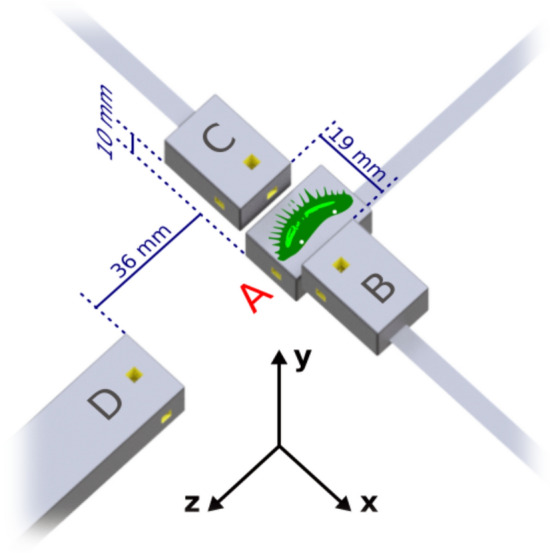
Figure 3.

Schematic of the experimental setup in the magnetically shielded room. The plant sample, an isolated lobe of the flytrap, is placed on top of primary sensor A, in the x–z plane with trigger hairs exposed. For reference, the dimensions of the housing (gray boxes) for the primary and secondary sensors are 24.4 × 16.6 × 12.4 mm3. Yellow cut-outs indicate the position of the 3 × 3 × 3 mm3 atomic sensing volume. A 3D-printed ABS plastic structure (not shown) holds the magnetometers in position on a wooden table. White dots on the plant sample, approximately 1 cm apart, indicate the placement of surface electrodes for AP monitoring. In the coordinate system shown, all magnetometers are sensitive along the y-axis, normal to the surface of the plant sample; furthermore, A and D are sensitive along the z-axis, and B and C are sensitive along the x-axis. Sensors B and C are positioned symmetrically around sensor A. Sensor D serves as a background sensor and is therefore located farther away from the sample.
