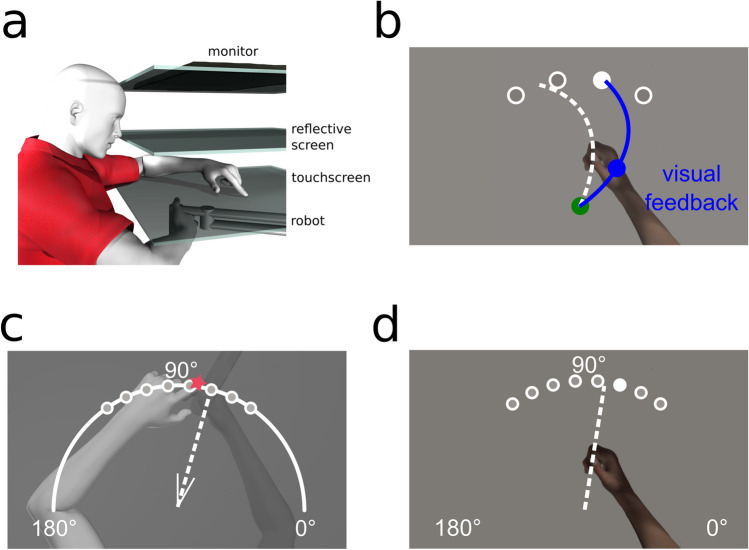
Figure 5.
Experimental setup and design. (a) Side view of the experimental set-up. The top layer is the monitor, middle layer is the reflective screen, and the bottom opaque layer is the touchscreen. The robot is depicted beneath with the participants’ right hand grasping it. (b–d) Top views of task specific set-ups. (b) Training (and Clamp) trial. The home position is represented by a green circle with a 1 cm diameter; located approximately 20 cm in front of the subject . Targets are represented by white circles with a 1 cm diameter located 12 cm radially from the home position at 60°, 80°, 100° and 120°. Participants hand cursor was also a 1 cm diameter blue circle. (c) Localization test trial. Participants were either passively moved to one of the eight target locations, or actively moved their hand in the direction suggested by the white wedge, consisting of two short straight lines (V-shaped) at the home position, these real and suggested locations are 55°, 65°, 75°, 85°, 95°, 105°, 115° and 125°. Subsequently, participants used a touch screen to indicate on a white arc spanning 180° where their unseen right hand was. (d) No-cursor test trial. Participants made ballistic reaches to one of the 8 target locations also used in localization without any visual feedback of their movement. Figures were made using Poser Rendering Software version 11, https://www.posersoftware.com/.

