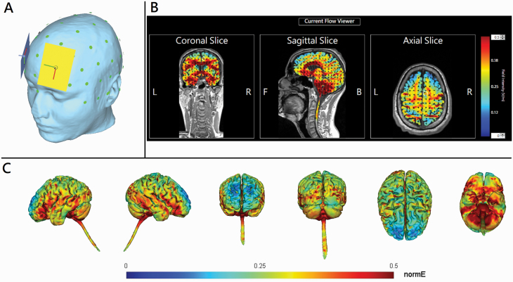
Figure 1.
(A) The head model of bi-anodal transcranial direct current stimulation (tDCS) over bilateral dorsolateral prefrontal cortex coupled with bilateral extracephalic references. The light green dots represent the international 10–20 electroencephalogram system of electrodes placement. The rectangles indicate 7- × 5-cm sponge electrodes. Yellow and blue colors represent first and second anodes, respectively. (B) 2D and (C) 3D representation of electric field simulation (HD-Explore, Soterix Medical, New York, NY). The red color indicates the strongest electrical field. Black arrows indicate the vectors of electrical current flow.

