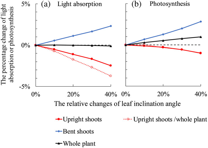
FIGURE 4.

The relative changes of simulated plant light absorption (a) and photosynthesis (b) with increasing leaf angles on upright shoots by 10, 20, 30 and 40%. Closed symbols with solid lines in each panel are results of comparing Scenario (iii) to Scenario (i) (in Table 1), where upright shoot architecture was obtained from the treatment in which focal plants had bent shoots and neighbour plants did not have bent shoots (F+N−). Open symbols with dotted lines in each panel are results of comparing Scenario (iv) to Scenario (ii) (in Table 1), where upright shoot architecture was obtained from the treatment in which both focal and neighbour plants did not have bent shoots (F−N−). In all panels, bent shoots are present in the simulation. Bent shoots are considered attached to the plants in simulations showing by closed symbols with solid lines. Bent shoots are considered independent of the plant in simulations showing by open symbols with dotted lines. The black dashed line in each panel indicates the level of 0% [Colour figure can be viewed at wileyonlinelibrary.com]
