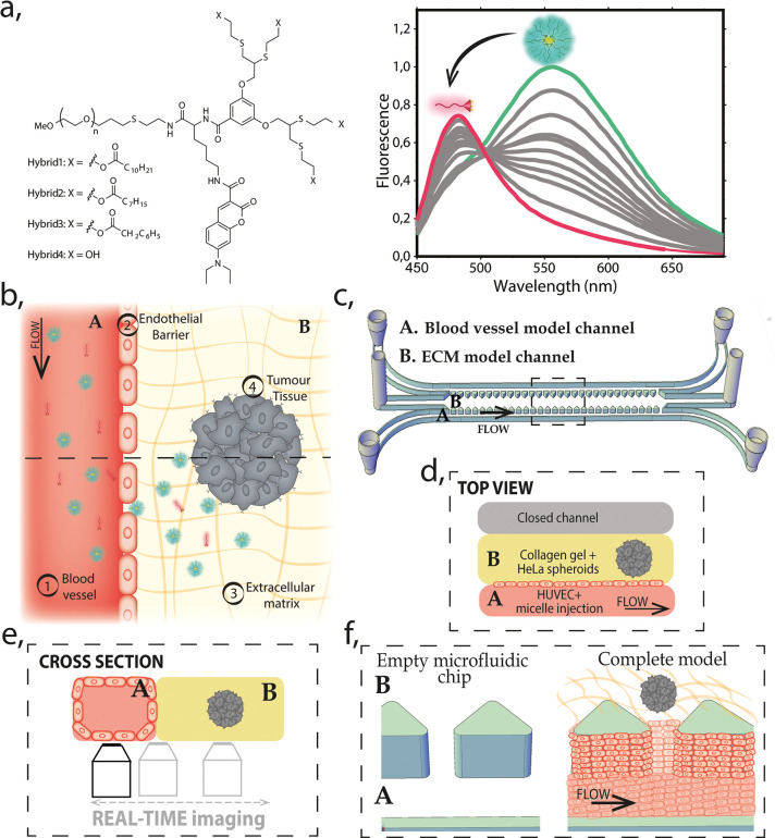
Figure 1.
Schematic representation of the model. (a) Molecular structure of the amphiphilic PEG–dendron hybrid polymers (left). Fluorescence emission graph for micelle–monomer equilibrium (right). In magenta, monomer (fully disassembled structure) and in green (fully assembled), micelle. (b) Schematic illustration of the top view of the model, with the reconstructed barriers marked as (1–4), two main regions (A, blood vessel channel and B, ECM model), and a cross-section indicated by dashed line for the projection of panel e. (c) 3D drawing of the microfluidic chip including inlets and outlets of each channel. A and B indicate two main compartments of the model: the blood vessel and ECM and the dashed-line marks area for the projection of the view in panel d. (d) Top view illustration of the microfluidic chip indicating the localization of the (A) blood vessel model channel and the (B) ECM model. The channel A is under continuous perfusion as schematically represented. (e) Cross-section illustration of the model (A and B, blood vessel/ECM model channels, respectively) and the scheme of the real-time imaging setup. (f) Zoom into the 3D representation (from panel c) showing the perspective of the channels before and after the complete model reconstruction. It illustrates how HUVECs line the blood vessel model channel covering the pillars and the collagen gel scaffold, forming a vertical endothelial barrier.

