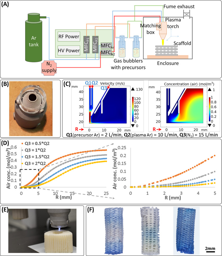
Fig. 5. An atmospheric plasma jet was adapted for the AM process, computational modeling assisted in optimizing gas flows for the process, and plasma-assisted patterning of 3D scaffolds was demonstrated.
The implemented plasma process consisted of a dual power supply and mass flow controllers for the plasma gas (Ar), shielding/cooling gas (N2), and two precursors in carrier gas (Ar) (A). The formation of a shielding gas shell around the reactive plasma flame was enabled by a nozzle cap (B), and the plasma and shielding gas ratio was optimized with the help of computational modeling (C, D). A combination of flow and diffusion modeling was used, as depicted by representative flow velocity and diffusion-affected concentration plots (C). The models showed that by increasing the flow of the shield gas relative to the plasma gas, a bigger inner volume could be shielded from air, as depicted by the air concentration falling to zero for a larger plasma radius (R), measured near the substrate (D). The plasma jet was integrated on the printer platform (E), and consecutive printing and plasma treatment layer-by-layer demonstrated the ability to plasma-treat a scaffold fully or at desired locations in 3D, as shown for uniform composition PEOT/PBT scaffolds coated with VTMOS–MAA and stained with methylene blue (F). The plasma-treated scaffolds shown in F are (from left to right) (i) bottom and top 10 layers plasma-treated, middle 20 layers non-treated; (ii) middle 10 layers plasma-treated, and top and bottom 15 layers non-treated; and (iii) all layers plasma-treated.

