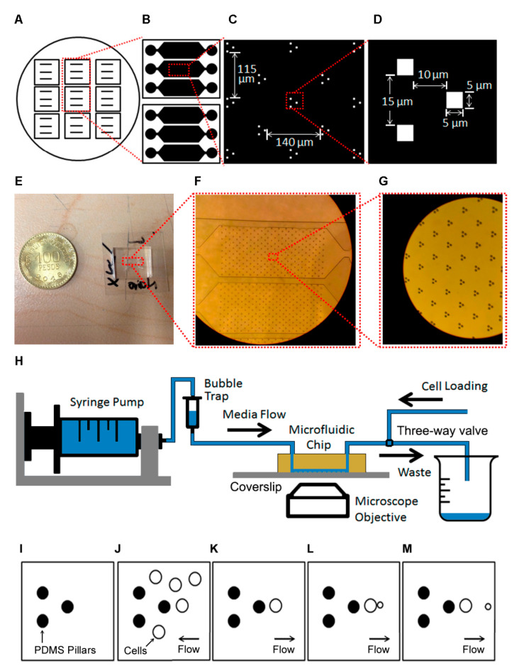
Figure 1.
(A) The circle represents a silicon wafer with masters for multiple devices. (B) Design of each chip, each with three independent channels. (C) Individual traps within a channel. We show the vertical and horizontal separations of each of the traps. (D) Individual trap dimensions. (E). Actual Microfluidic Chip compared with a Colombian Coin. (F) Zoom-in of the channels. (G) Zoom-in of the pillars. (H) Sketch of the experimental setup. (I–M) Sketch of trap operation. (I) Empty trap. (J) Concentrated cells are inserted through the outlet. (K) Normal flow is started, and only cells that are in the trapping area remain. (L) Cells grow and reproduce. The flow directs budding cells to the right. (M) When the daughters detach, the flow takes them away.

