
Fig. 4.
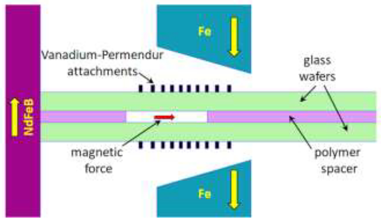
Schematic of the cross section of the Micro DMF II channel placed between the magnet pole pieces, pushed into contact with the surface of the magnet block on the left. The Vanadium Permendur attachments are seen on each side of the channel. The direction of magnetization of the magnet block (NdFeB) and pole pieces (Fe) are indicated by the yellow arrows.