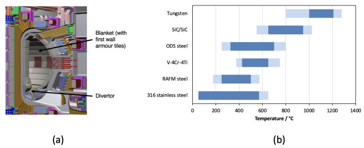
Figure 1.
(a) Cross section of the ITER tokomak, showing location of first wall, blanket and divertor structures. (b) Operating temperature windows (based on radiation damage and thermal creep considerations) for selected fusion candidate materials. The light shaded bands on either side of the dark bands represent the uncertainties in the temperature limits. This figure is a modified version of that first presented in Reference [8].

