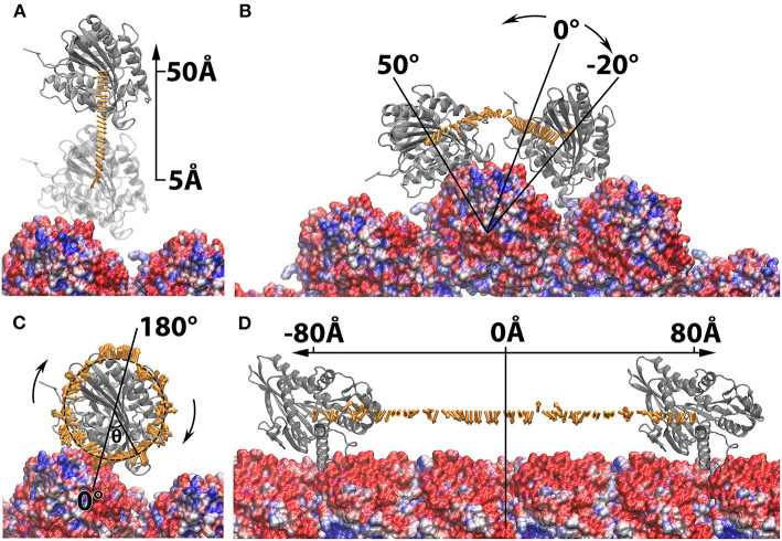
Figure 6.
Electrostatic forces between the manipulated kinesin motor domain and microtubule while the kinesin motor domain is (A) separated from the microtubule from 5Å to 50Å in 2Å interval; (B) rotated around one chosen microtubule unit form −20Å to 50Å in 2Å interval; (C) spun from −180Å to 180Å in 2Å intervals around the z-axis. (D) Translated along the microtubule from −80Å to 80Å in 2Å interval. The kinesin motor domains are shown in ribbon. The microtubule are shown in surface colored from red to blue in a scale of −3.0 to 3.0 kT/Å. The electrostatic forces are represented by arrows. In (C), the arrow tails are place on a circle where the spinning degrees can be differentiated by the angle theta (θ), while the tails of arrows in all other panels are placed at the mass centers of the manipulated capsomers. The force arrows in each panel are normalized to the same size. All images are rendered by VMD.

