. 2021 Jan 26;10:e60936. doi: 10.7554/eLife.60936

Figure 1. Flexible and accurate reduction methodology.

(A) For any set of locations on a given morphology (left, here an L2/3 pyramidal cell [Branco and Häusser, 2010]), a reduced compartmental model can be derived (middle), with an associated schematic representation (right). (B) Steps of our approach: (1) choice of locations at which the reduced model should reproduce the full model’s voltage, (2) coupling, leak and channel conductances are fitted to resistance matrices derived from the full model at different holding potentials, and (3) capacitances are fitted to mimic the largest eigenmode of the full model. (C) The resistance matrix of the passive full model (top) restricted to the five locations in A is approximated accurately by the inverse of the conductance matrix of the passive reduced model (bottom). Labels correspond to locations in A. (D) Example components of the quasi-active resistance matrix of the full model, equipped with a Na+-channel, as a function of the holding potential vh. Red lines show the four holding potentials at which our methodology evaluates the resistance matrix. Singularities correspond to holding potentials where the linearization is invalid and should be avoided in the fit. Labels correspond to locations in A. (E) Temporal shape of exemplar input impedance kernels of the full model (gray) and their reduced counterparts (blue, dashed). (F) Same as in E, but for transfer impedance kernels.

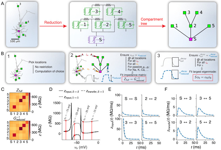
Figure 1.

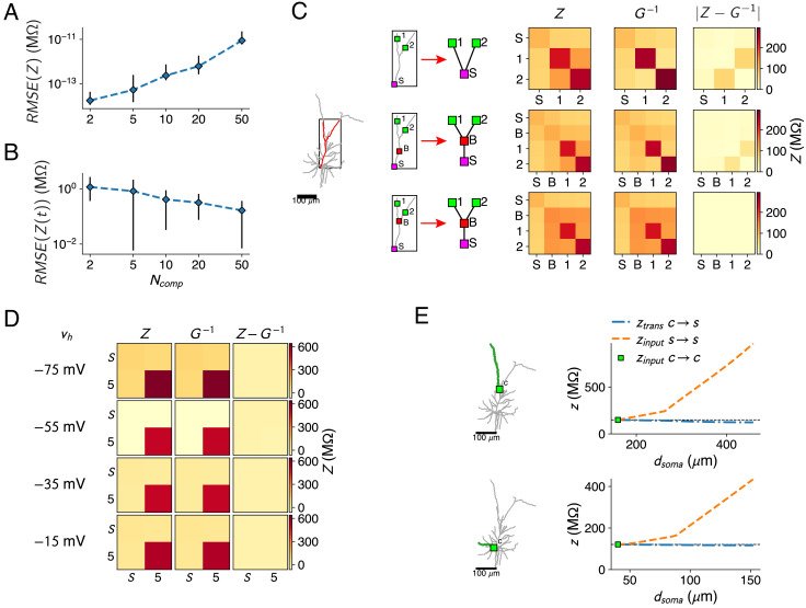
Figure 1—figure supplement 1. Resistance matrix fit details.

Figure 1—figure supplement 1.

(A) Error of the reduced model’s resistance matrix compared to the full model’s resistance matrix, for reductions of the passive L2/3 pyramid with 2, 5, 10, 20, and 50 compartments. Five random sets of fit locations were chosen for each compartment number; mean (marker) and standard deviation (error bars) are shown. (B) Same as A, but for the impedance kernels. (C) The bifurcations between compartment sites need to be added, as shown in the red forked dendrite (left). Soma S and two compartment sites 1, 2 (top) were augmented with a site B on the main trunk (but not at a bifurcation, middle) or a site B at the bifurcation (bottom). Reductions were derived for all three configurations, but only the last configuration can accurately approximate all resistances (right). (D) Resistance matrices for the soma S and location five in Figure 1A, with Na+-channels at the soma. The resistance matrix Z (first column) depends on vh. The inverse of the matrix G (second column) is fitted by adjusting the maximal Na+ conductance parameter so that ZG=I at the four holding potentials. G-1 matches Z closely, as the difference between both matrices is close to zero (third column). (E) Behavior of the input and transfer resistances between a compartment site c (green square) and a synapse site s located more distally on the same subtree (only a single branch is shown for clarity, marked in green). Transfer resistance between c and s remains close to the input resistance at c, while input resistance at s increases markedly with distance. This principle holds in the apical (top) as well as basal (bottom) dendrites.