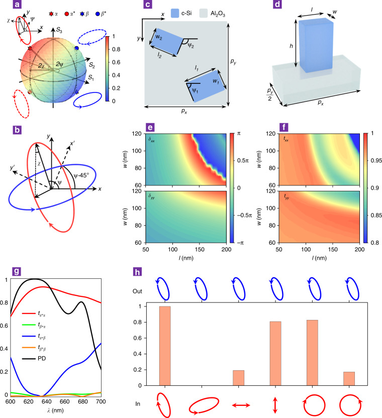
Fig. 2. Metasurface design for APCD.
a Poincaré sphere representation of an arbitrary orthogonal polarization pair (α, β) (solid red and blue ellipses) and its handedness-flipped pair (α*, β*) (dashed red and blue ellipses). b Defined local coordinate system x’oy’ (dashed lines) that is rotated by ψ-45° with respect to the global xoy coordinate, in which the axes pass through cross points of the polarization ellipses of α and β. c Schematic of metamolecules on the metasurface consisting of asymmetrically dimerized nanopillars. The periods are px = py = 340 nm, and the orientation angles and positions of the two nanopillars are ψ1 = ψ-45° and ψ2 = ψ and (3px/4, 3py/4) and (px/4, py/4), respectively, where ψ is the main axis angle of the modulated polarization ellipse. d Single nanopillar unit cell for determining phase retardations along its length and width, as shown in e. The height of the nanopillar was fixed at 300 nm. e Phase retardations and f transmission coefficients upon varying the length l and width w of the nanopillar at a wavelength of 633 nm for the x-polarized (upper panels) and y-polarized (lower panels) incident light. g Polarization conversion coefficients and PD spectrum calculated with the optimized parameters (l1 = 130 nm, w1 = 70 nm; l2 = 150 nm, w2 = 85 nm) at a wavelength of 633 nm, which yields tα*α = 0.93 and tβ*α = tα*β = tβ*β ≈ 0. h, Transmitted polarization states (blue ellipses) when the metasurface was illuminated by a variety of different incident polarization states (red curves). The histogram indicates the transmittance, which varied with the incident polarization, while the shape of the blue ellipse was the same as that of the designed polarization state α*.

