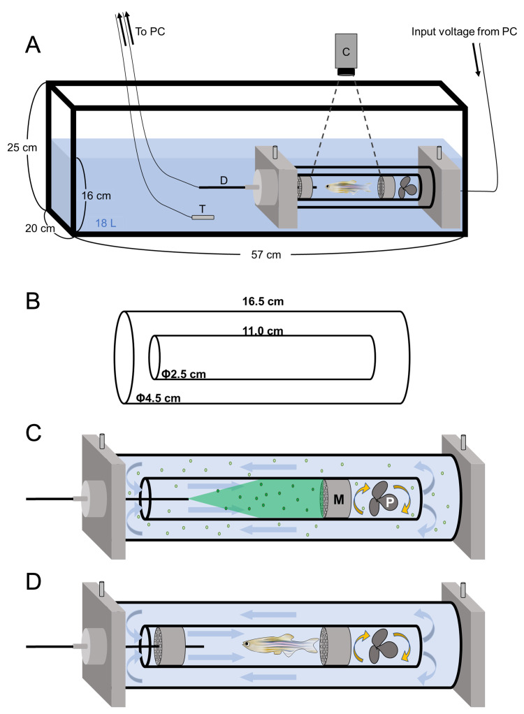
Figure 1. Structure of the swimmill.
A. The schematic diagram of the Swim Tunnel Respirometer. C: high speed video camera; D: dissolved oxygen densitometer, T: thermometer. B. Size of the double cylinder. C. An enlarged view of the double cylinder. The propeller rotation generates a directional water flow in the double cylinder. Fluorescent beads flow in the double cylinder and glitter by receiving the excitation light from the green laser pointer. M: mesh; P: propeller. D. In the presence of water flow, zebrafish keep swimming by the same speed with water velocity to stay at the same position. Two plastic meshes were put in the swimming chamber to avoid the fatigued fish hit the propeller.

