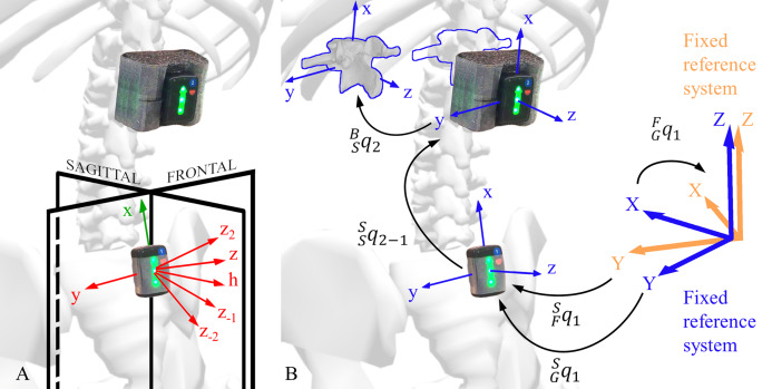
Figure 3. Explanation of the kinematic constraints and rotations between different reference systems.
(A) Representation of sensor axes and kinematic constraints axes. The sensor local reference system is shown in green, the kinematic constraints axes are shown in red, and the global reference system planes are shown in black. (B) Segment angle (SGq1) and a joint angle (SSq2−1) orientation. The sensor angle orientation (SFq1) with respect to the fixed reference system (blue), the fixed reference system (orange) orientation (FGq1) with respect to the global reference system, and body reference system orientation with respect to the sensor reference system (BSq2) are shown.

