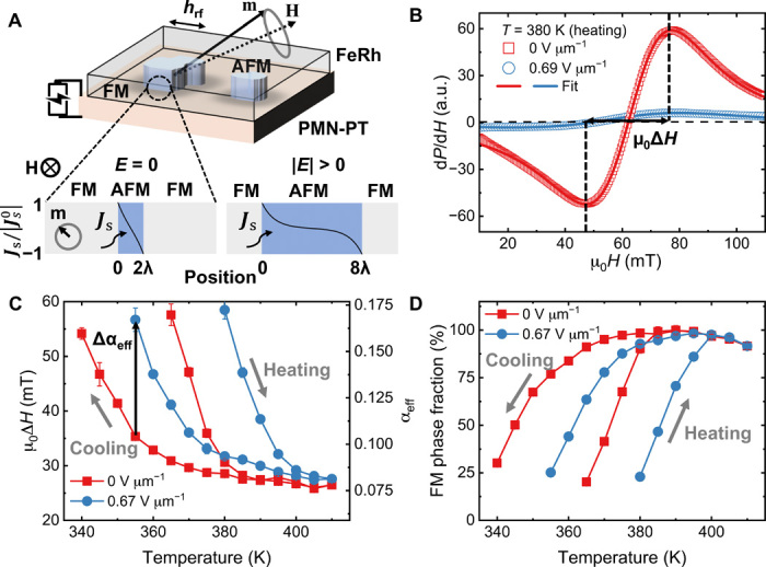
Fig. 1. Tuning mechanism of the magnetic damping in FeRh/PMN-PT.

(A) Schematic illustration of the FeRh/PMN-PT heterostructure where the antiferromagnetic (AFM) domains embedded in the ferromagnetic (FM) matrix of FeRh were driven into FMR by microwave magnetic fields hrf. The electric field (E) was applied across the thickness direction of the PMN-PT substrate to induce piezo strains. Bottom schematics show the isothermal growth of antiferromagnetic domains in the FeRh under relatively large electric fields. The curves in the blue region represents the profile of spin current density across the lateral direction of the antiferromagnetic domain, where || is the magnitude of spin current density at the ferromagnetic/antiferromagnetic interface; λ is the spin diffusion length in the antiferromagnetic domain. a.u., arbitrary units. (B) FMR spectra and the fittings of the FeRh/PMN-PT at 380 K during heating with applied electric fields of 0 (red) and 0.67 V μm−1 (blue), respectively. (C) Temperature dependence of the resonance linewidth μ0ΔH and the corresponding effective magnetic damping αeff with applied electric fields of 0 (red) and 0.67 V μm−1 (blue), respectively. (D) Temperature dependence of the ferromagnetic phase fraction with applied electric fields of 0 (red) and 0.67 V μm−1 (blue), respectively.
