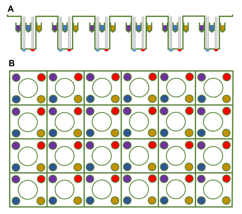
Figure 2. Schematic of the probe plate.

The (A) side-view and (B) top-view of the 24-well sensor cartridge, where the sensor is in the center and the injection ports for compounds are in the periphery of each well. Pick the same injection port, which would be the ports of the same color, for each well when adding a compound.
