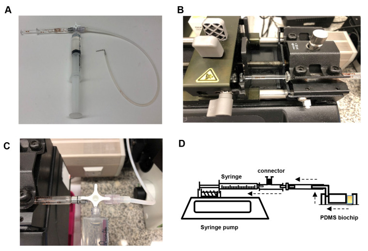
Figure 2. Setup of the syringe pump.
A. Assembly of the 2 ml glass syringe, plastic 20 ml syringe filled with water (to flush the tubing after each experiment) and tubing (with a 1 mm diameter metal adapter) on a 3-way stopcock connector. B. Assembly of glass syringe on the pump. C. Rotation of the stopcock to enable flow from tubing to glass syringe. D. Schematic of the microfluidic chip set-up. Dashed arrows indicate the direction of flow. The yellow square in the chip represents the platelet suspension.

