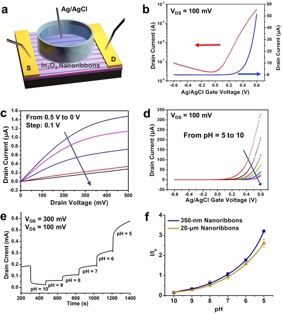
Figure 4. (a).
Schematic illustration of a liquid state measurement where a Ag/AgCl electrode serves as the top-gate. Transfer (b) and output (c) characteristics of 350-nm-wide In2O3 nanoribbon field-effect transistors (FETs) in the liquid-gate setup shown in (a). (d) Transfer curves of 350-nm-wide In2O3 nanoribbon FETs in solutions of pH 10 to 5. (e) Real-time current responses from a representative 350-nm-wide In2O3 nanoribbon FET exposed to commercial buffer solutions of pH 10 to 5. (f) Current responses relative to baseline for solutions of pH 10 to 5 using 350-nm- or 20-μm-wide ribbon In2O3 FETs. I/I0 is current normalized to the baseline pH before the experiments (I0, pH = 7.4). Error bars are standard errors of the means with N=3 FETs for each configuration.

