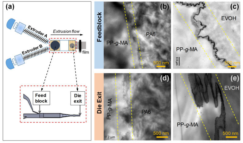
Figure 10.
(a) Schematic of the coextrusion device with feedblock and die exit system. TEM micrographs of interfacial morphology for (b) PP-g-MA/PA6 and (c) PP-g-MA/EVOH bilayers quenched after leaving the feedblock and for (d) PP-g-MA/PA6 and (e) PP-g-MA/EVOH bilayers quenched after leaving the die exit. The area sandwiched between parallel dashed lines in (b–e) indicates the interfacial regions. Reprinted with permission from Ref. [83]. Copyright (2020) American Chemical Society.

