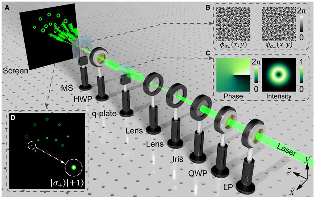
Figure 1. Schematic illustration of the experimental setup for optical spin and angular momentum detection.

(A) The green helicoids and red arrow indicate phase fronts and polarization state respectively. Optical elements: LP (linear polarizer), QWP (quarter-wave plate), HWP (half-wave plate) and MS (metasurface). (B) Designed phase distribution for LCP (left inset) and RCP (right inset) light from 0 to 2π in the central area of the functional metasurface used for demultiplexing. (C) Calculated phase (left inset) and normalized intensity (right inset) distribution of incident vortex beam generated by the q-plate. (D) Calculated intensity distribution on screen when incident with a vortex beam of spin and angular momentum state |σ+〉|+1〉.
