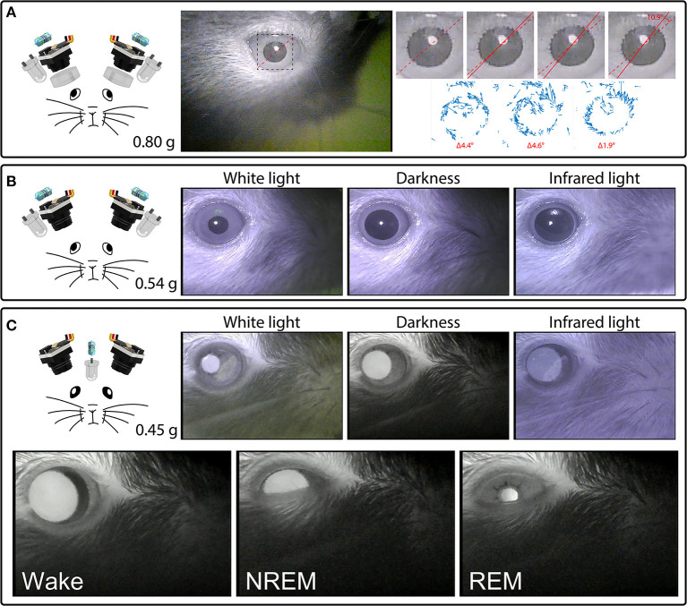
Figure 4.
Headset components pictured with their total weight (left) and examples of their video signals (right). (A) A camera headset consisting of two camera modules, resistors, external IR LEDs, and collimating lenses (left), and an example frame from Supplementary Video 4, showing the right eye (middle). The inset marks the cropped location of the enlarged images of the pupil (right) from four consecutive deinterlaced frames of Supplementary Video 4 at 60 Hz, with optic flow vector fields between successive frames shown underneath. Dashed red lines mark the orientation of prominent serrations across the pupillary rim of the iris in the first frame. Solid red lines track these serrations in consecutive frames. See Supplementary Video 4 for the full video. Optic flow was calculated in Matlab using the Lucas-Kanade derivative of Gaussian method with a noise threshold of 0.0005, and plotted with a scale factor of 100. (B) A camera headset consisting of two camera modules, resistors and external IR LEDs (left), and example frames of the video signals produced under white houselights, no houselights (darkness), and infrared houselights (right). See Supplementary Video 4 for example footage under white houselights. (C) A camera headset consisting of two camera modules, one resistor, and one IR LED chronically implanted above a cranial window for infrared back-illumination pupillometry (iBip), and example frames of the video signals produced under white houselights, no houselights (darkness), and infrared houselights (top right). See Supplementary Video 4 for example footage under white houselights, and Supplementary Video 5 for example footage in darkness, displaying the fundus, and optic disc. Example frames of wake, NREM sleep, and REM sleep recorded in the nest of the home cage (bottom). See Supplementary Video 6 for the full video.

