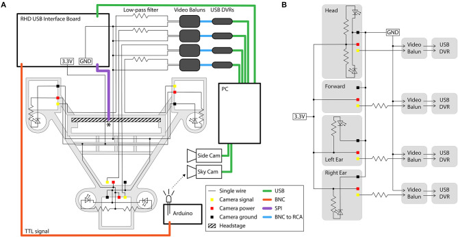
Figure 7.
Circuit diagram and connections for the four-camera headstage-integrated headset. (A) The camera carrier (same as Figure 2Aiii) is shown in the background in gray. The RHD 32-channel headstage is represented by the hatched rectangle, and is attached to its associated SPI cable represented by the purple line at the point marked *. TTL pulses sent to the RHD 2000 USB Interface Board are relayed through a BNC cable (orange) to an Arduino Uno for synchronization of electrophysiology and video signals by illumination of an IR LED in view of the webcam placed above the arena (the SkyCam). Yellow, red, and black squares represent the soldering locations on the camera modules for the signal, power, and ground wires. Low-pass filters are constructed on a breadboard, and are then connected to video baluns through a BNC connection. From the video baluns, the signal passes through a BNC to RCA connection (blue) to the USB DVRs. Green lines represent USB cables. Black dots indicate logical connections of signals and components; for true solder locations, see the instructions in the Appendices. (B) Conventional circuit diagram for powering and signal processing of the analog cameras, same circuit as shown in (A) but without illustration of cable type or spatial layout.

