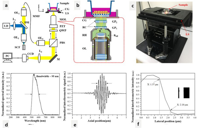
Figure 7.
(a) Experimental setup of the Mirau-based FF-OCT for cell imaging. LD: 445-nm laser diode; L1: 40× aspheric lens; DM: dichroic mirror; OL1 and OL2: 40× and 20× objective lenses; SCF: single-clad crystal fibre; MMF: multimode fibre (NA: 0.39); OL3: 20× objective lens (NA: 0.4); PBS: polarising beam splitter; QWP: quarter-wave plate; PZT: piezo-electric transducer; MOL: home-designed Mirau objective lens; LS: transversal linear stage, CG; cover glass; M: mirror; L2: tube lens (focal length: 150 mm); CCD: charge-coupled device. (b) Schematic illustration of the MOL with OL: 20× water immersion objective lens; GP1 and GP2: the first and second glass plates; noil: refractive index of silicon oil (n = 1.406); RC: reflection coating; RH: ring holder; B: 420-µm-diameter black absorber spot. (c) Photograph of the Mirau-based FF-OCT. (d) The emission spectrum of Ce3+:YAG SCF. (e) and (f) are the axial and lateral resolutions of 0.9 and 0.8 µm, respectively. The inset of (f) is the resolution test target imaged by FF-OCT.

