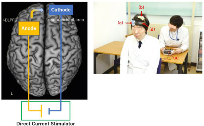
Figure 1.
Schematic diagram (Left) and experimental setup (Right) for tDCS. (Left) The anode and cathode electrodes are positioned over the left dorsolateral prefrontal cortex and over right supraorbital region, respectively. The direction of current flow is from the anode to cathode. (Right) An administrator controls the stimulator (a). Anodal (b) and cathodal (c) electrodes of 35-cm2 in size are placed on F3 and right supraorbital region, respectively. A head strap (d) is used as needed to increase reproducibility.

